HOW TO RELOCATE A SINK DRAIN AND VENT LINE: 3 METHODS FOR SLAB AND CRAWLSPACE FOUNDATIONS
Relocating a sink during a kitchen or bathroom remodel involves far more than simply extending water supply lines. The primary challenge lies in correctly routing the waste drain and vent lines to maintain proper drainage velocity, prevent sewer gas entry, and comply with standard building codes. Depending on whether your home is built on a crawlspace or a concrete slab foundation, the labor, structural disruption, and plumbing configurations will vary significantly.
Below is an overview of three structural methods for running new drain lines to a relocated sink, along with critical building code principles to keep in mind.
FOUNDATION CONSIDERATIONS: CRAWLSPACE VS. SLAB ON GRADE
Before choosing a routing path, you must evaluate the existing foundation type.
Crawlspace Foundations
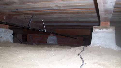
If your home features a crawlspace, relocating a sink is relatively straightforward. Plumbing lines are accessible beneath the floor joists. You can tap into the primary DWV (Drain, Waste, and Vent) branch line under the home, run a new branch line with a continuous 1/4-inch per foot slope, and extend it up through the subfloor into the new wall cavity.
Slab-on-Grade Foundations
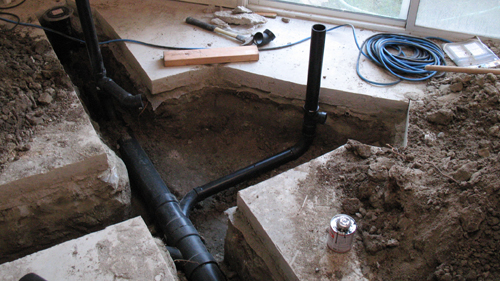
When working with a concrete slab foundation, you cannot simply route pipes under the subfloor. Instead, you must either saw-cut the concrete slab to bury new drain lines in the sub-base or route pipes above-grade through wall framing. Trenching through concrete requires removing the slab section, excavating soil, laying pipe at proper slope, backfilling with well-compacted gravel or soil, and re-pouring the concrete patch.
METHOD 1: TYING INTO THE MAIN INDOOR DRAIN LINE THROUGH THE SLAB
For a sink relocation on a slab foundation, the most direct subterranean route is tying into an existing 3-inch or 4-inch main indoor soil pipe.
Execution Steps:
Saw-cut and remove a trench through the concrete floor from the main drain line to the new sink location.
Install a 4x2 or 4x1-1/2 combination wye and 1/8 bend (combo sweep fitting) into the main line, oriented in the direction of waste flow.
Run a 2-inch or 1-1/2-inch ABS or PVC drain line through the trench toward the new wall, maintaining a minimum slope of 1/4-inch per foot.
Transition from the horizontal floor line into a vertical stack inside the wall cavity using a long-turn elbow.
Install a sanitary tee at the proper height (typically 16 to 18 inches above the finished floor) to create the trap arm connection for the sink.
Extend the top of the sanitary tee upward through the top plate to connect to an existing vent stack or exit through the roof.
METHOD 2: ROUTING OUTSIDE THE EXTERIOR FOOTING AND SLAB
If cutting across a large section of interior slab is impractical or cost-prohibitive, you can route the drain line along the interior wall, penetrate through the exterior wall or footing, and tie into the main sewer line outside the home.
Execution Steps:
Core-drill or chip out an opening through the exterior wall/footing near floor level to pass the new drain line to the exterior.
Connect to the main exterior sewer line using a combination wye fitting, sloping the pipe at 1/4-inch per foot back toward the exterior connection.
Install a cleanout fitting at the exterior transition or base of the stack to allow for future snake or hydro-jet access.
Rise vertically into the new wall cavity with long-sweep elbows, transitioning into a vertical drain-vent stack with a sanitary tee for the sink trap arm.
Note: Exterior pipe penetrations must be thoroughly sealed and insulated where local climate conditions expose pipes to freezing temperatures.
METHOD 3: WALL-ROUTED EXTENDED TRAP ARM (WITH DEDICATED VENTING)
In multi-story construction where penetrating a concrete slab or floor structure is impossible, contractors sometimes consider running a long horizontal pipe through the wall framing back to an existing vent or drain stack.
However, strict building code rules govern the maximum distance a trap arm can run before reaching a vent. Under both the International Residential Code (IRC) and Uniform Plumbing Code (UPC), an unvented trap arm for a 1-1/2-inch pipe is strictly limited in length (maximum 6 feet under IRC, or 3 feet 6 inches under UPC).
If you attempt to run a long horizontal drain line inside a wall cavity over a distance of 10 to 13 feet, you CANNOT simply extend the trap arm. Doing so creates an unvented siphoning hazard. To make an above-grade horizontal run work across longer distances, you must convert the installation into a properly vented horizontal branch line:
The sink trap must connect directly to a vertical pipe section fitted with a sanitary tee.
A dedicated vent must extend upward from the top of that tee (either connecting to a roof vent or using an approved Air Admittance Valve where permitted).
The bottom of the tee then drains into a properly sloped 2-inch horizontal branch drain line hidden inside a furred-out wall cavity that routes back to the main stack.
THREE KEY CONSTRUCTION TIPS
Maintain Precise Pipe Slope: Always slope horizontal DWV drain lines (2 inches or smaller) at a strict minimum of 1/4-inch fall per linear foot. Insufficient slope causes solids to settle out of suspension, leading to clogs. Excessive slope can cause liquid to flow faster than solid waste, leaving debris behind.
Account for Structural Wall Thickness When Furring Out: Standard 2x4 interior wall studs (3.5 inches actual depth) cannot accommodate a 3-inch or 4-inch DWV pipe without violating structural framing codes regarding stud notch and hole limits. If running pipes horizontally through walls, build a dedicated 2x6 plumbing wall or furr out the wall framing to preserve structural integrity.
Install Accessibility Cleanouts at Major Directional Changes: Whenever a drain line makes a directional change greater than 135 degrees, or runs across a long horizontal distance, install an accessible cleanout tee. Even if a removable P-trap serves as a primary access point under the sink, an exterior or wall-mounted cleanout prevents expensive wall demolition during future main-line snaking.
BONUS QUESTIONS AND ANSWERS
Question 1: Can I notch 2x4 wall studs horizontally to run a 2-inch sink drain pipe to a new location?
Understanding structural framing limits and building codes is critical when altering load-bearing or non-load-bearing walls for plumbing.
Under IRC Section R602.6, boring or notching studs is strictly regulated to prevent structural collapse. For a 2-inch PVC/ABS pipe (which has an actual outside diameter of 2.375 inches), cutting a hole or notch through a standard 2x4 stud (3.5 inches wide) removes over 67% of the stud's depth. Building codes limit non-bearing wall notches to a maximum of 40% of stud depth (45% for bored holes, or up to 60% if double studs are used and steel shoe plates are installed). Therefore, you cannot run a 2-inch drain line horizontally straight through standard 2x4 framing studs. You must build a 2x6 plumbing wall, run the pipe beneath the slab/floor joists, or furr out the wall to accommodate the pipe diameter safely.
QUESTION 2: WHY DOES NATURAL STONE TILE REQUIRE A STIFF FLOOR FRAMING SYSTEM THAN CERAMIC OR PORCELAIN TILE?
TRANSITION:
Once your plumbing layout is secured, it is equally important to evaluate whether your existing framing can handle the weight and rigidity of your chosen flooring material.
ANSWER AND STRUCTURAL REASONING:
Natural stone tiles (such as marble, granite, slate, or travertine) are much more brittle and far less flexible than standard ceramic or porcelain tiles, making them vulnerable to cracking under minor floor movement.
Building codes and Tile Council of North America (TCNA) guidelines specify strict deflection limits:
Standard ceramic and porcelain tile installations require a maximum floor joist deflection of L/360 under total design load (where L equals the span of the joist in inches).
Natural stone tile installations require a much stricter maximum deflection limit of L/720.
Under L/360, a 12-foot floor joist span is allowed to bend up to 0.4 inches under full weight. While ceramic tile can often withstand slight flexing, that same 0.4-inch bend will cause natural stone and its grout joints to snap and shear due to low flexural strength. Achieving L/720 usually requires doubling up floor joists, reducing joist spacing from 16 inches on-center to 12 inches on-center, or adding an extra layer of exterior-grade plywood subflooring before installing cement backer board.
Question 3: Is an Air Admittance Valve (AAV) a code-compliant alternative when you cannot run a traditional vent stack through the roof?
When structural constraints prevent you from running a physical pipe up through upper floors or out the roof, understanding modern mechanical venting rules provides a safe path forward.
Under IRC Section P3114, Air Admittance Valves (AAVs, commonly known by brand names like Auto-Vents or Studor Valves) are code-compliant single-way mechanical valves designed to allow air into the DWV system when negative pressure occurs during drainage. This breaks the vacuum and protects the P-trap seal without requiring a pipe penetration through the roof. However, AAVs must be installed vertically at least 4 inches above the horizontal cold-water trap arm, placed in an accessible space with adequate airflow (such as inside a sink cabinet), and cannot serve as the sole venting point for a building's overall drainage system at least one main vent stack must extend open to the outdoor air. Always check local plumbing amendments, as some strict jurisdictions (such as those strictly following older UPC revisions) limit or restrict AAV usage.