Construction And Building Drawings For Carpenters
The ability to accurately read and interpret construction and building drawings is a foundational skill for any professional carpenter. These documents serve as the definitive instruction manual for a build, translating architectural vision into structural reality. Without a thorough understanding of blueprints, structural integrity and building code compliance are instantly compromised. This guide explores the essential components of construction drawings, equipping carpentry professionals with the knowledge to execute projects flawlessly.
Understanding Blueprint Basics
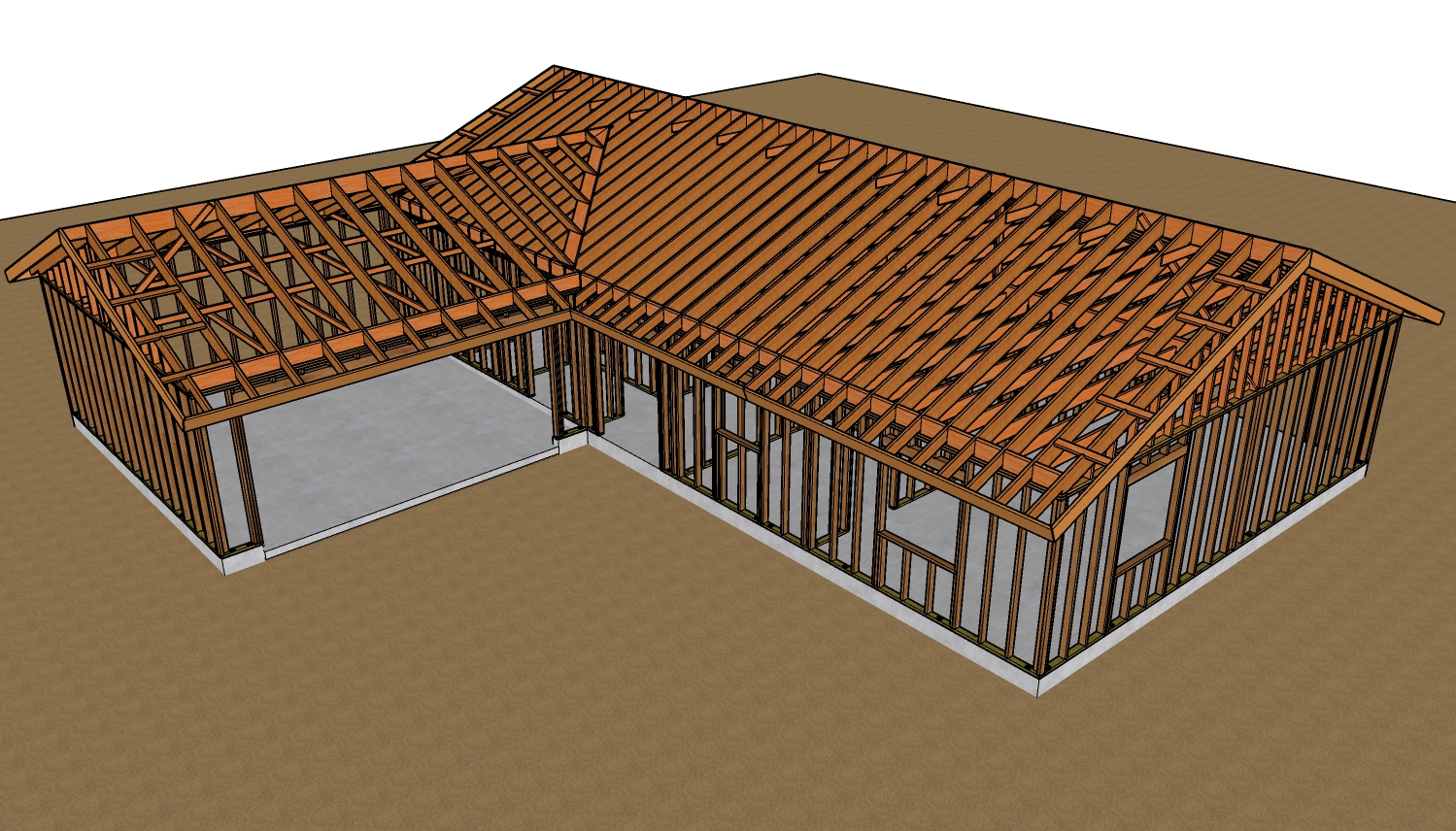
Construction drawings are typically organized in a specific sequence to guide the builder from the ground up. A standard set includes site plans, foundation plans, floor plans, elevations, sections, and detail drawings. Carpenters primarily focus on framing plans, floor plans, and sections. Floor plans provide a bird's-eye view of the layout, dictating wall placement, door and window rough openings, and room dimensions. Section drawings slice vertically through the building, revealing the internal wall assemblies, floor joist spans, and roof pitch requirements crucial for framing.
Decoding Symbols And Abbreviations
Blueprints utilize a universal language of symbols and line types. Solid, thick lines typically denote visible object outlines like framed walls, while dashed lines often indicate hidden elements or features above, such as a drop ceiling or a cantilevered beam. Carpenters must be fluent in identifying symbols for load-bearing walls, shear walls, and specific structural hardware. Familiarity with standard abbreviations is equally critical to prevent costly layout errors on the job site.
The Importance Of Scale And Dimensions
Because building drawings cannot be printed at life size, they are drawn to scale. A common architectural scale used in residential framing is one-quarter inch equals one foot. While an architect's scale ruler is a helpful tool, carpenters should always rely on the explicitly written dimensions rather than scaling the drawing manually with a ruler. If a written dimension contradicts the visual scale, the written number always takes precedence. Consulting the architect or structural engineer is the best practice for unresolved discrepancies.
Conclusion
Mastering construction and building drawings ensures that a carpenter can confidently translate plans into durable, code-compliant structures. By understanding floor plans, recognizing symbols, and strictly adhering to written dimensions, builders minimize errors and maximize on-site efficiency.
Three Key Tips For Reading Construction Drawings
Always verify the title block. Before starting any layout, check the title block to ensure you are working from the most recent revision date. Building plans go through multiple iterations, and framing off an outdated set can lead to massive tear-outs and structural code violations.
Trust written dimensions over scaled measurements. Paper blueprints can stretch, shrink, or be printed out of scale. Never use a tape measure on the paper to determine a critical framing dimension; always use the numerical dimension provided by the designer.
Cross-reference architectural and structural pages. Architectural floor plans show the aesthetic layout, but structural pages specify the required header sizes, beam spans, and load-path blocking. Both must be reviewed together to ensure compliance with gravity and lateral load requirements.
Bonus Questions And Answers
To further expand your understanding of building plans beyond the core concepts, here are a few advanced questions frequently asked by carpentry professionals.
What Is The Difference Between A Live Load And A Dead Load On A Structural Drawing?
Structural drawings often reference live and dead loads to dictate joist and beam sizing. A dead load refers to the constant, immovable weight of the building materials themselves, such as the framing, roofing, and drywall. A live load represents the variable weight of occupants, furniture, and environmental factors like snow. The International Residential Code mandates that floor systems be designed to support a minimum live load, typically forty pounds per square foot for general living spaces, to ensure the structure does not deflect or fail under daily use.
Why Do Blueprints Specify Engineered Lumber Instead Of Dimensional Sawn Lumber For Long Spans?
Plans frequently call for laminated veneer lumber or I-joists in specific locations rather than traditional sawn lumber. Engineered wood products are manufactured to eliminate natural defects like knots and warping, offering superior strength and predictability. Building codes govern the maximum allowable spans for dimensional lumber based on species, grade, and spacing. When an open floor plan requires a span exceeding those limits, structural engineers specify engineered lumber to safely carry the loads without impermissible deflection.
How Do Building Codes Regulate Fastener Schedules On Framing Blueprints?
Structural drawings often include a detailed nailing schedule, particularly for shear walls and roof decking. The spacing and type of fasteners are not suggestions; they are rigorously calculated requirements designed to resist shear forces from wind and seismic activity. For example, an engineer might specify nailing edge blocking every four inches instead of the standard six. Deviating from this schedule can compromise the structural diaphragm and result in a failed framing inspection under current international building standards.