REPLACING GARAGE RAFTER TIES WITH CEILING JOISTS: STRUCTURAL GUIDELINES
INTRODUCTION
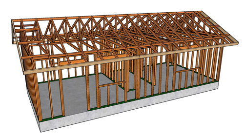
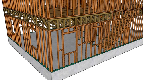
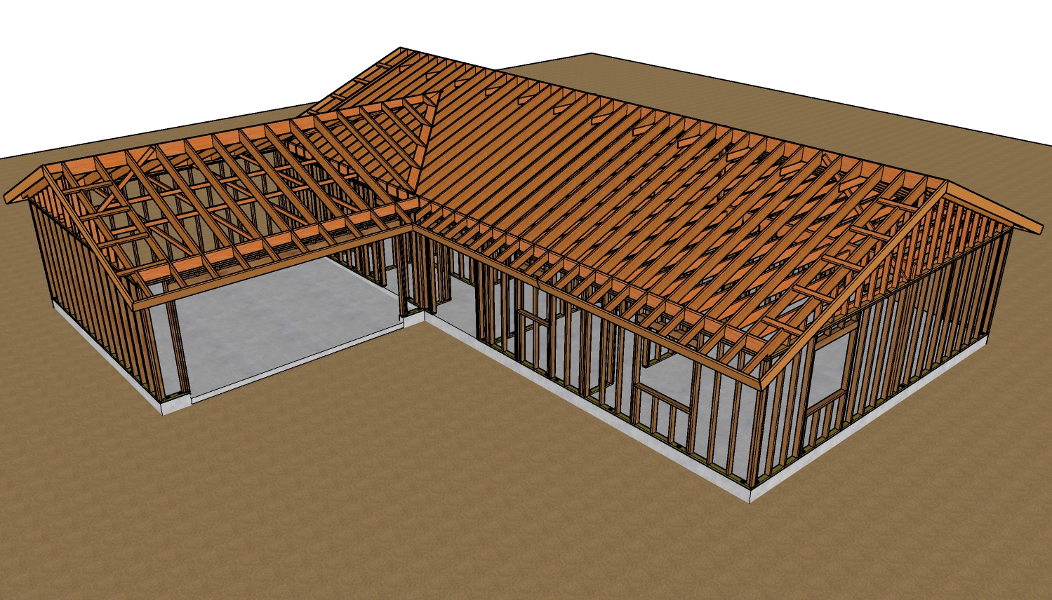
When modifying a garage roof structure, upgrading from standard rafter ties to full ceiling joists is a common structural improvement. However, installing larger lumber in an existing roof space presents specific geometric and structural challenges. Because the larger joists must fit within the existing roof pitch, the ends of the boards often interfere with the roof sheathing, necessitating modifications that must comply with strict residential building codes.
THE CHALLENGE OF ROOF CLEARANCE
Substituting larger lumber for standard rafter ties means the new boards will take up more vertical space. As the ceiling joists rest on the top plate of the exterior wall, the upper corners of these boards will often protrude past the roofline.
To allow the roof sheathing to sit flush, the top edge of the joist ends must be tapered or notched. While tapering seems like a simple woodworking task, it directly impacts the load-bearing capacity of the joist and is heavily regulated by structural guidelines.
NAVIGATING THE BEARING POINT AND NOTCHING LIMITS
The most critical location on a ceiling joist is the bearing point, which is the exact location where the joist rests on the interior face of the wall plate. According to standard International Residential Code (IRC) guidelines, you cannot remove more than one-quarter of the depth of a joist at its bearing point.
For example, if you are using an eight-inch joist, the maximum allowable notch or taper depth at the bearing point is two inches. Removing more material than allowed compromises the shear strength of the joist and can lead to structural failure. The measurement must be taken exactly at the inside edge of the supporting wall, not at the extreme outer end of the board.
ALTERNATIVE FRAMING SOLUTIONS
If the required taper exceeds the one-quarter depth limit, you must employ alternative structural solutions rather than violating building codes. There are a few standard methods to solve clearance issues:
REDUCE JOIST SIZE AND SPACING: Instead of using large joists spaced 24 inches on center, you can often achieve the same structural capacity by using smaller boards spaced closer together. For instance, transitioning from deep joists at 24 inches on center to slightly shallower joists at 16 inches or 12 inches on center may provide the necessary roof clearance while maintaining the required load capacity according to standardized span tables.
INSTALL A SUPPORT LEDGER: Adding a ledger board securely fastened to the wall studs beneath the joists can shift the bearing point inward. By moving the bearing point away from the roof slope, you gain vertical clearance and change where the one-quarter depth rule applies. This method relies heavily on the shear strength of the fasteners (such as heavy-duty lag bolts). Because this modifies the transfer of structural loads, it must always be designed and approved by a licensed structural engineer and your local building department.
CONSTRUCT A LOAD-BEARING WALL: Building a new load-bearing wall directly beneath the joist span can provide mid-span support, drastically reducing the required joist depth. However, any new load-bearing wall must transfer its weight to an adequate foundation or footing, meaning concrete excavation and pouring may be required.
CONCLUSION
Upgrading garage rafter ties requires careful calculation and strict adherence to building codes. Never arbitrarily cut or notch structural lumber without verifying the depth limits at the bearing points. When existing roof constraints make standard joist installation impossible, consulting span tables for alternative spacing or hiring a structural engineer for modified bearing solutions ensures the roof remains safe, compliant, and structurally sound.
THREE KEY TIPS
ADHERE TO THE ONE-QUARTER RULE: Never remove more than 25 percent of a ceiling joist's total depth at the bearing point. Exceeding this limit severely reduces the structural integrity and shear capacity of the lumber.
MEASURE AT THE INSIDE BEARING FACE: When calculating your maximum allowable taper or notch, take your measurement at the exact point where the joist passes over the inside edge of the supporting wall top plate.
ADJUST SPACING BEFORE COMPROMISING WOOD: If clearance is tight, consult standard structural span tables to see if using shallower lumber spaced at 12 or 16 inches on center can safely carry the load instead of improperly over-cutting larger lumber.
BONUS QUESTIONS AND ANSWERS
To further expand on the complexities of modifying roof structures, here are a few additional structural considerations that go beyond basic joist installation.
QUESTION: DO CEILING JOISTS REQUIRE BLOCKING OR BRIDGING TO PREVENT TWISTING?
ANSWER: Yes. According to standard building codes, joists that exceed a certain depth-to-thickness ratio require solid blocking, diagonal bridging, or a continuous wood structural panel fastened to the top edge to prevent lateral displacement and rotation. Even for smaller joists, installing solid blocking over the bearing points helps maintain the vertical alignment of the lumber under load, ensuring the weight transfers directly downward into the wall plate rather than buckling laterally.
QUESTION: CAN I USE STANDARD WOOD SCREWS TO SECURE THE CEILING JOISTS TO THE WALL PLATES?
ANSWER: No. Standard construction screws or drywall screws lack the necessary shear strength and are brittle, meaning they can easily snap under lateral loads. Building codes require the use of approved framing nails (such as 16d common nails) or specialized structural screws (like engineered timber screws or approved hurricane ties) to secure joists to top plates. This ensures the connection can withstand uplift from wind and the outward thrust forces generated by the roof load.