INTRODUCTION
Successfully coordinating residential plumbing layout with structural framing is one of the most critical phases of residential construction. When drain lines and vent stacks conflict with joists and rafters, uneducated field modifications can severely compromise the structural integrity of a home. Conversely, poorly planned plumbing runs can lead to chronic clogs, improper venting, and code violations. This article explores a code-compliant framework for integrating subfloor plumbing, managing tight spatial tolerances, laying out wet vent systems, and executing structural modifications safely.
INTEGRATING PLUMBING AND STRUCTURAL FRAMING
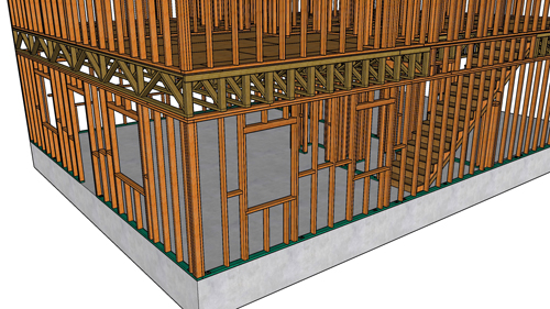
A common challenge in bathroom framing occurs when a partition or load-bearing wall sits directly over a floor joist, precisely where vertical plumbing drains must drop. Doubling the joist directly underneath the wall is standard framing practice to support the structural load. However, running large-diameter waste lines through a solid double joist is virtually impossible without destroying its structural integrity.
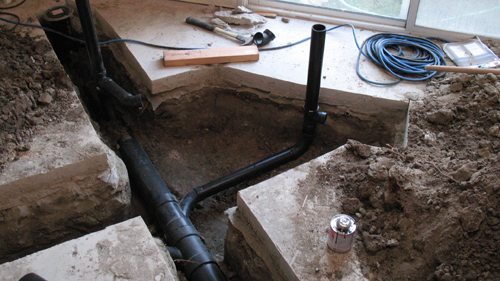
To resolve this issue, tradespeople can replace the continuous double joist with solid structural blocking spaced sequentially between adjacent joists. This blocking successfully transfers the vertical wall loads down to the foundation while leaving open cavities between the blocks. These openings provide dedicated pathways for the toilet and bathtub drains to drop vertically into the crawlspace or basement without requiring destructive drilling through structural members.
When establishing the subfloor layout, strict attention must be paid to spatial tolerances. For instance, maintaining a clearance of nine inches from the rough framed wall to the inside face of the nearest joist is exceptionally tight for standard bathtub drain assemblies. Utilizing scaled architectural drawings during the design phase is essential to identify these spatial bottlenecks before framing begins, preventing costly field retrofits.
OPTIMIZING BATHROOM WASTE AND VENT LAYOUTS
A highly efficient method for plumbing a standard bathroom layout involves configuring the toilet drop into a vertical waste line that simultaneously functions as a wet vent. In this configuration, a single vent pipe provides air circulation to protect the traps of multiple fixtures.
For the secondary fixtures, such as the bathroom sink, the drain line connects directly to the vertical wet vent using a code-approved sanitary tee. When sizing and running horizontal trap arms to the vent stack, plumbing codes dictate strict length limitations to prevent self-siphoning of the fixture trap:
Under the Uniform Plumbing Code (UPC), an inch-and-a-half drain line is limited to a maximum developed length of 42 inches from the trap weir to the vent fitting.
If the layout requires a longer horizontal run, upgrading the pipe diameter to two inches increases the maximum allowable trap arm distance to 60 inches.
SMART CLEANOUT DESIGN FOR EASY MAINTENANCE
Integrating accessible cleanouts into the waste system provides cheap insurance against future diagnostic and maintenance headaches. Cleanout fittings should match the diameter of the drain line they serve.
For a centralized bathroom stack, the cleanout should be positioned above the finished floor level and oriented to face into the room rather than behind the toilet fixture. Placing a cleanout behind a toilet is counterproductive, as the technician would be forced to pull the toilet off its wax ring to service the line, rendering the cleanout redundant.
Furthermore, when plumbing branch lines for appliances located near perimeter walls, such as a washing machine drain assembly, cleanouts should be positioned to face the exterior of the building. In the event of a severe main line stoppage, wastewater will back up into the vertical pipe. If the cleanout cap faces inward, unscrewing it will flood the finished interior spaces with greywater. Orienting the cleanout to open toward the exterior ensures that any pressurized backup discharges harmlessly outside the home.
FRAMING MODIFICATIONS AND ROOF VENT ROUTING
Running vent stacks vertically through the roof envelope offers an invaluable maintenance benefit. It allows plumbers to clear stubborn main-line blockages by running a mechanical drain auger down through the roof vent stack, avoiding the need to crawl underneath the structure.
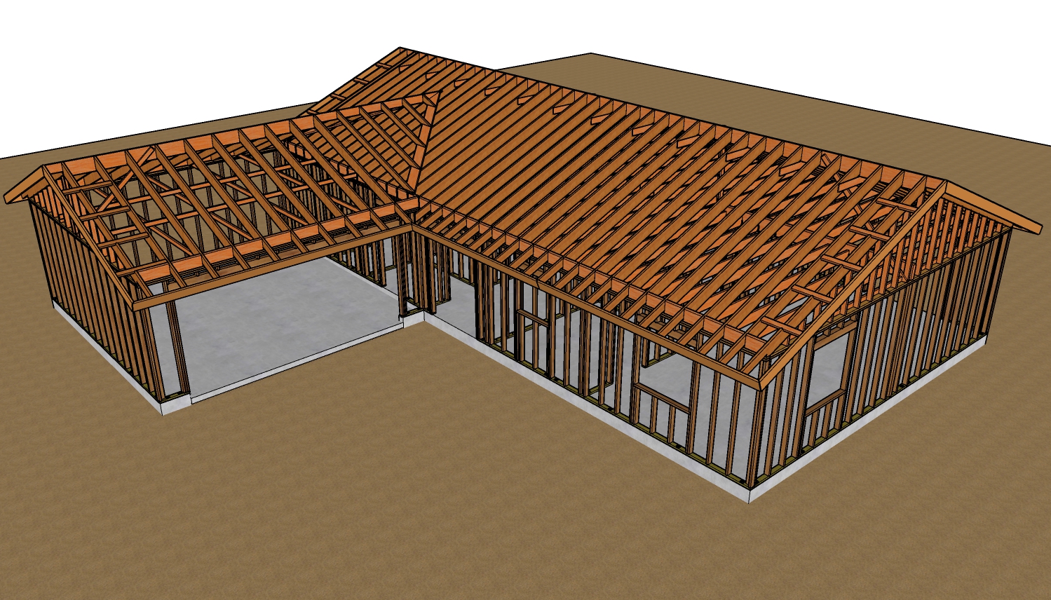
However, routing these pipes vertically requires careful navigation of the roof framing. Notching structural framing members is heavily regulated by building codes. Notching the bottom or top of a standard roof rafter is only permissible if that specific rafter is fully supported along its entire length by a gable end wall and structural gable studs. In this localized scenario, the vertical studs bear the structural load, making the notch non-destructive.
Conversely, mid-span rafters carrying active roof loads must never be notched or altered without structural engineering approval. Where a vent pipe directly conflicts with a mid-span rafter, the plumbing must be offset around the framing member. Utilizing a pair of 22-degree or 45-degree directional fittings allows the vent line to jog smoothly around the structural timber without restricting critical airflow or compromising the roof structure.
CONCLUSION
A successful build requires proactive communication between the framing layout and the plumbing design. By utilizing structural blocking instead of solid doublers, adhering strictly to code-mandated trap arm lengths, and routing vents safely around active roof framing, builders can ensure a structurally sound, highly functional, and fully code-compliant home. Always verify your localized layouts with the local building department to ensure compliance with regional amendments.
THREE KEY TIPS FOR PLUMBING AND FRAMING INTEGRATION
Substitute continuous double joists with spaced solid blocking beneath walls containing vertical plumbing drops to maintain load distribution while preserving pathways for large waste lines.
Upgrade horizontal trap arm diameters from an inch-and-a-half to two inches if the layout requires the fixture trap to sit farther than 42 inches from the vent stack.
Orient perimeter waste cleanouts to open toward the building exterior to prevent accidental indoor flooding during drain cleaning operations.
BONUS QUESTIONS AND ANSWERS
QUESTION: What are the strict code limitations for drilling or notching load-bearing floor joists to accommodate plumbing lines?
ANSWER: While modifying framing is occasionally necessary to route piping, cutting into load-bearing floor joists requires strict adherence to structural codes to prevent catastrophic sagging or structural failure. According to Section R502.8 of the International Residential Code (IRC), notches made in solid lumber joists are strictly prohibited within the middle third of the span. Outer-third notches cannot exceed one-sixth of the actual joist depth, and notches at the very ends of the joist are limited to one-fourth of the depth. Furthermore, any bored holes must be located a minimum of two inches away from the top or bottom edges of the joist, and the diameter of the hole cannot exceed one-third of the total depth of the joist.
QUESTION: Why must a sanitary tee never be installed horizontally to connect a horizontal waste line transition?
ANSWER: Beyond managing pipe distances, selecting the correct fitting geometry is vital for code compliance and long-term drainage performance. Both the International Plumbing Code (IPC) and the Uniform Plumbing Code (UPC) strictly prohibit the use of a sanitary tee to transition a horizontal flow to another horizontal flow, or a vertical flow to a horizontal flow. A sanitary tee has a short, abrupt radius designed solely to guide vertical drops into horizontal lines or to vent horizontal runs. Utilizing it horizontally causes solid waste to lose velocity, leading to frequent material buildup and clogs. Instead, code requires a combination wye and eighth bend or a long-sweep quarter bend to provide a smooth, sweeping transitional radius for horizontal waste flow.
QUESTION: What is the minimum slope required for horizontal drainage piping, and why is an excessive slope actually harmful to the system?
ANSWER: Once the plumbing layout is configured safely around the structural framing, establishing the precise pitch for the horizontal waste lines is the final step in ensuring system reliability. Building codes dictate that horizontal drainage pipes two inches or less in diameter must maintain a minimum downward slope of 1/4 inch per foot toward the main sewer link (IRC Section P3005.3). While establishing a slope is necessary to harness gravity, an excessive pitch exceeding 1/2 inch per foot on small-diameter lines is highly detrimental. Liquid waste moves at a much higher velocity than solid waste; an excessive slope causes the water to race ahead, leaving solids stranded at the bottom of the pipe, which creates recurring, severe blockages.