ROOF FRAMING AND PLUMBING INTEGRATION FOR A 434-SQUARE-FOOT HOME
Building a high-quality compact home requires strategic space planning and precise execution. When working within a 434-square-foot footprint, structural framing and mechanical systems must fit together seamlessly without compromising structural integrity or building code compliance. This guide breaks down the essential structural framing steps for the roof system alongside the distribution design for the supply and drain-waste-vent (DWV) plumbing lines.
ADVANCED ROOF FRAMING AND GABLE END STRATEGIES
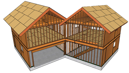
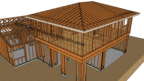
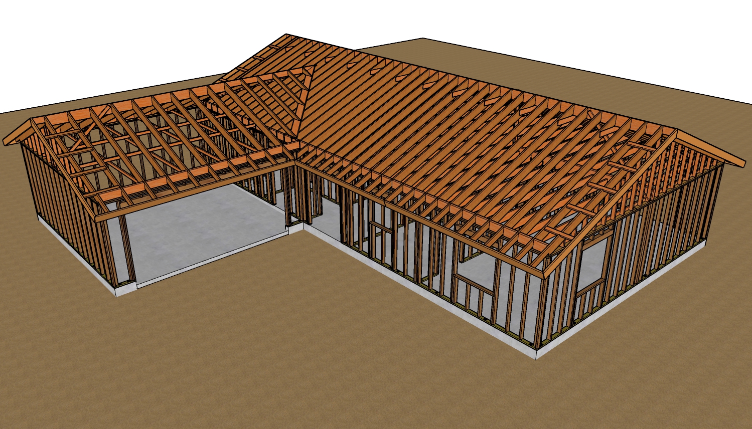
The structural skeleton of this small home uses 2x6 roof rafters spaced at 24 inches on center. When framing the gable end walls, the installation method chosen for the drywall backing dictates the layout of your gable studs.
If 2x4 flat backing is installed horizontally along the top plate, the bottom of the vertical gable studs must be notched to seat over the backing. To eliminate this time-consuming step and maintain full structural lumber depth, a superior alternative is to install the 2x4 backing upright, orienting it in the same direction as the ceiling joists. This allows the backing to be nailed directly to the faces of the gable studs, which are spaced at 16 inches on center starting from the center of the wall.
For homes requiring a gable-end louver for attic ventilation, the layout must be modified. Rather than starting a stud directly in the center, offset two central gable studs to create a rough opening that accommodates the vent chassis while providing necessary vertical support for the ridge board.
To tie the gable wall rigidly into the ceiling diaphragm, 2x6 blocking is positioned between the rafters. These blocks can be painted before or after the roof sheathing is fastened. Structural stability is enhanced by driving toenails through the ceiling blocks into the wall framing top plate and face-nailing the upright backing into the blocking. Alignment straps can be installed across these blocks to anchor the system further. For short roof spans, such as an 8-foot rafter run, a standard sub-fascia or finish fascia board can be installed directly across the rafter tails without structural lookouts, though local wind load requirements should dictate final sub-fascia detailing.
EFFICIENT RESIDENTIAL PLUMBING LINE DESIGN
Integrating mechanical routing into a small footprint requires keeping pipe runs consolidated to maximize pressure efficiency and minimize framing conflicts.
WATER SUPPLY NETWORKS: COPPER AND PRESSURE LOGIC
The pressurized water distribution network utilizes rigid copper piping. The main water supply line enters the building footprint through the floor system, where a main shut-off valve must be installed immediately. This main line feeds directly to a tankless water heater station.
To maintain balanced water pressure and adequate volume when multiple fixtures run simultaneously, a 3/4-inch main distribution line should be run from the water heater all the way to the primary bathroom cluster. Once at the bathroom, the 3/4-inch line terminates into a reducing tee, splitting into 1/2-inch branch lines that feed the individual fixtures: the shower valve, the water closet (toilet), and the lavatory (sink). Standard professional plumbing practice dictates that hot water supply lines route to the left side of fixtures, and cold water supply lines route to the right.
DRAIN-WASTE-VENT (DWV) NETWORK: ABS PIPING AND FRAMING INTEGRATION
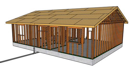
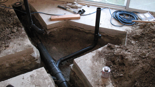
The gravity-fed drainage and vent systems utilize black ABS (Acrylonitrile Butadiene Styrene) piping. A critical junction in the drainage network is the inclusion of accessible cleanouts. Positioning a primary cleanout where the main stack transitions below the slab allows a plumber to clear obstructions all the way through the perimeter footprint to the sewer tie-in.
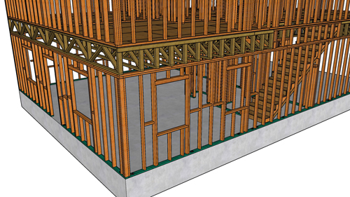
When routing vertical waste stacks through wood-framed walls, structural limitations dictate pipe placement. A standard 2-inch or 3-inch ABS pipe cannot be drilled through the structural trimmers or king studs of a rough window opening without severely compromising the header support. Instead, route the vertical wet vent or waste line completely outside of the window framing bay. If the pipe extends slightly past the finished drywall profile, it can easily be concealed within the cavity of the kitchen or bathroom base cabinets.
For the ventilation system, a combined wet-venting strategy can be deployed. By maintaining a 2-inch pipe diameter for the lavatory waste line and vent, the single pipe can safely serve as the vent for both the sink and the toilet. Where the horizontal fixture drain meets the vertical vent stack, a sanitary tee must be oriented correctly to ensure smooth pneumatic exhaust out through the roof sheathing.
ROOF SHEATHING AND FINISHING
The roof structure is enclosed using structural panels like OSB (Oriented Strand Board) or exterior-grade plywood. For exposed rafter tails or open eave details where the underside of the sheathing remains visible from the exterior, utilizing an exterior-grade, paintable plywood finish ensures long-term weather resistance and clean aesthetics.
THREE KEY ACTIONS FOR STRUCTURAL AND PLUMBING ACCURACY
OPTIMIZE GABLE BACKING ORIENTATION: Install 2x4 drywall backing upright parallel to the ceiling joists instead of flat against the top plate. This avoids the need to notch the bottom of your gable studs, preserving the full structural integrity of the lumber and speeding up framing.
MAINTAIN VOLUMETRIC SUPPLY SIZING: Run a minimum 3/4-inch main water supply line from your water source or water heater to the main bathroom drop before reducing down to 1/2-inch lines at individual fixture tees. This prevents drastic pressure drops and temperature fluctuations when plumbing fixtures are used simultaneously.
ISOLATE WASTE RAMP CAVITIES FROM STRUCTURAL JAMBS: Never drill large-diameter drainage holes through window king studs or trimmers. Route vertical ABS drain-waste-vent lines completely clear of window rough openings, utilizing cabinet voids or dedicated plumbing chases to conceal the pipes without weakening load-bearing framing.
BONUS QUESTIONS AND ANSWERS
While planning your layout, it is helpful to look at how specific structural requirements and code mandates affect your framing and plumbing designs.
QUESTION 1: Why is it structurally dangerous to notch the middle third of a roof rafter or floor joist when routing utility pipes?
ANSWER: Under the International Residential Code (IRC Section R502.8 for joists and R802.7 for rafters), notches are strictly prohibited in the middle third of any structural spanning member. The middle third of a span experiences the highest bending moments and tension forces along the bottom edge of the wood fibers. Notching this zone removes critical material where tension stress is concentrated, dramatically increasing the risk of deflection, sagging, or catastrophic structural failure. Notches at the ends of structural members cannot exceed one-fourth of the member depth, and notches in the outer thirds are capped at one-sixth of the total depth.
QUESTION 2: What determines whether a 2-inch ABS pipe can serve as a common vent for both a toilet and a bathroom sink?
ANSWER: The International Residential Code (IRC Section P3105) permits common venting and wet venting provided the total fixture unit load does not exceed code limits and the pipe diameters are sized accordingly. A toilet typically rates at 3 Drainage Fixture Units (DFUs) and a bathroom sink at 1 DFU. According to wet-vent sizing tables, a 2-inch pipe is required to vent a maximum load of 4 DFUs when a water closet is included in the bathroom group. If you reduce the vent pipe to 1.5 inches, it violates code because a 1.5-inch wet vent can only support a maximum of 1 DFU and cannot adequately balance the pneumatic pressure changes caused by a toilet flush.
QUESTION 3: When installing horizontal ABS drainage lines behind a wall or under a floor, what is the mandatory slope requirement to prevent clogging?
ANSWER: The International Residential Code (IRC Section P3005.4) mandates that horizontal drainage piping with a diameter of 2.5 inches or less must be installed with a minimum continuous slope of 1/4 inch per foot (approximately a 2% grade) toward the point of disposal. This specific slope is crucial for proper hydraulics: it ensures that liquid waste flows at a velocity high enough to carry solid waste along with it. If the slope is too shallow, solids will settle and cause blockages; if the slope is too steep, the liquids can outrun the solids, leaving debris behind to dry and clog the line.