BUILDING A STEM WALL FOUNDATION AND RAISED FLOOR FRAMING SYSTEM
Building a solid foundation is the critical first step in ensuring the structural longevity of any small home or accessory dwelling unit. While solid concrete slab foundations are common, a raised floor system supported by concrete stem walls offers distinct advantages, particularly regarding utility accessibility and moisture management. This comprehensive guide outlines the process of assembling a stem wall foundation and framing a raised floor system, focusing on standard building layout procedures, structural reinforcement, and optimal framing practices.
FOUNDATION DIMENSIONS AND CRAWL SPACE ACCESS
The foundation construction process begins with digging and forming the perimeter footings. For a standard small residential structure, the concrete footings are excavated to a width of 12 inches and a depth of 12 inches. Built directly on top of these footings are the concrete stem walls, which stand 18 inches tall and are formed to a width of 6 inches.
A critical element of any stem wall foundation is the integration of a crawl space access hole. This opening ensures that plumbing, electrical wiring, and mechanical systems remain fully accessible for future maintenance or repairs. According to general building standards, the minimum structural requirement for a crawl space access opening is 18 inches tall by 24 inches wide. To build this into the foundation, wooden block-outs are constructed to the desired dimensions and securely anchored between the interior and exterior foundation formwork prior to pouring concrete.
REBAR REINFORCEMENT AND ANCHOR BOLT PLACEMENT
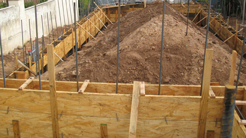
Structural strength is achieved by integrating steel reinforcement within the concrete. This system utilizes number 4 rebar, which has a diameter of 0.5 inches. To protect the steel from environmental moisture and subsequent corrosion, the rebar must be suspended and centered between the forms, maintaining a clear distance of 2 to 3 inches from the wooden formwork. The structural design features a continuous bottom rebar running through the footing, while the upper horizontal bars terminate cleanly at the crawl space access block-out.
When overlapping rebar sections to create continuous structural runs, proper lap splicing is vital. A standard engineering rule of thumb dictates that rebar should overlap by a minimum of 40 times its diameter. For half-inch rebar, this establishes a minimum lap length of 20 inches, though utilizing a conservative 24-inch lap provides an extra margin of structural continuity.
Before the concrete is poured, anchor bolts must be strategically positioned. These bolts secure the wooden framing to the concrete foundation. A vital structural rule is that anchor bolts must be placed within 12 inches of any break or joint in the pressure-treated sill plate framing. Care must also be taken during layout to ensure the anchor bolts are positioned to avoid direct conflict with the future locations of the floor joists.
FLOOR JOIST FRAMING AND VENTILATION
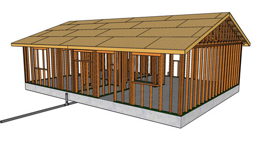
Once the concrete stem walls have cured and the formwork is stripped, the wooden framing phase begins. Pressure-treated sill plates are attached to the top of the concrete walls via the anchor bolts. Floor joists are then installed across the span. At the mid-span of the floor system, structural blocking is installed between the joists to prevent them from twisting under load. Staggering these mid-span blocks rather than placing them in a perfectly straight line allows for direct, efficient face-nailing through the sides of the joists.
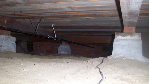
Proper crawl space ventilation is necessary to control moisture accumulation and prevent wood rot. Openings are cut into the rim joists to accommodate foundation vents. When planning the layout of these vents, it is critical to cross-reference the architectural drawings to ensure that external features, such as outdoor stairways, porches, or decks, will not cover or obstruct the ventilation openings in the future.
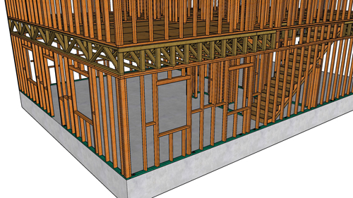
Where interior walls run parallel to the direction of the floor joists, additional structural support is required underneath. Instead of doubling up the floor joists which can make running vertical plumbing pipes and waste lines exceptionally difficult solid wood blocking can be installed horizontally between the joists beneath the wall footprint. This blocking method provides the necessary structural load paths while leaving open bays for mechanical installations. The framing is completed by fastening a high-quality three-quarter inch subfloor, such as Oriented Strand Board (OSB) or plywood, across the top of the joist network.
THREE KEY ACTIONS FOR FOUNDATION AND FRAMING SUCCESS
MAINTAIN REBAR CLEARANCE: Always ensure that number 4 rebar is suspended with a minimum of 2 inches of concrete coverage from the edges of the formwork to prevent moisture penetration and long-term structural degradation.
POSITION ANCHOR BOLTS STRATEGICALLY: Place anchor bolts within 12 inches of every sill plate joint or break, and explicitly map out their placement so they sit in the bays between the scheduled floor joist locations.
STAGGER MID-SPAN BLOCKING: Stagger the layout of mid-span bridging blocks rather than aligning them perfectly. This allows for straight, solid face-nailing through the joist rather than weaker toe-nailing.
BONUS QUESTIONS AND ANSWERS
Moving beyond the specific layout steps covered in the construction sequence, successful field execution relies heavily on adhering to strict structural engineering standards and regional building codes. Below are three critical technical questions regarding code compliance and structural science for raised floor systems.
QUESTION: What is the minimum required distance between the bottom of the floor joists and the ground inside a crawl space, and what is the structural reason for this rule?
ANSWER: According to the International Residential Code (IRC Section R317.1), un-treated wood floor joists must be positioned a minimum of 18 inches above the exposed earthen ground within a crawl space, and wood girders/beams must be at least 12 inches above the ground. The structural reasoning behind this code is moisture control and the prevention of fungal decay. Exposed soil constantly releases water vapor through capillary action and evaporation. Maintaining an 18-inch clearance creates an adequate air buffer that, when combined with proper ventilation, prevents the relative humidity adjacent to the wood framing from reaching the threshold required for wood-destroying fungi to grow. It also provides the minimum clearance necessary for visual inspections regarding termite activity.
QUESTION: How do building codes determine the minimum total area required for crawl space ventilation openings, and how should they be distributed?
ANSWER: IRC Section R408.1 dictates that the minimum net free ventilating area must be at least 1 square foot for each 150 square feet of under-floor space area. However, this required ratio can be reduced to 1 square foot for every 1,500 square feet if the ground surface is completely covered with an approved Class I vapor retarder (such as 6-mil polyethylene sheeting). Structurally, these vents must be placed as close to each corner of the building as possible to eliminate "dead air" zones where stagnant, humid air can pool. Providing cross-ventilation ensures continuous air movement, which carries away evaporated ground moisture before it can absorb into the floor framing system.
QUESTION: Why do building codes enforce a strict minimum embedment depth for anchor bolts in a concrete stem wall, and what is that standard depth?
ANSWER: Standard residential building codes (IRC Section R602.11) require anchor bolts to have a minimum diameter of 1/2 inch and to be embedded at least 7 inches into the concrete foundation. The structural reasoning is to resist both shear forces (lateral sliding caused by wind or seismic activity) and uplift forces (the house trying to lift off the foundation due to wind pressures). A shallow embedment would result in a "concrete cone failure," where the localized tension stress pulls a small chunk of concrete out of the wall. Embedding the bolt a minimum of 7 inches deep engages a much larger volume of the concrete matrix, ensuring the mechanical connection can transfer the full design loads from the wood framing down into the earth.